Installing 3-Way Ball Valves
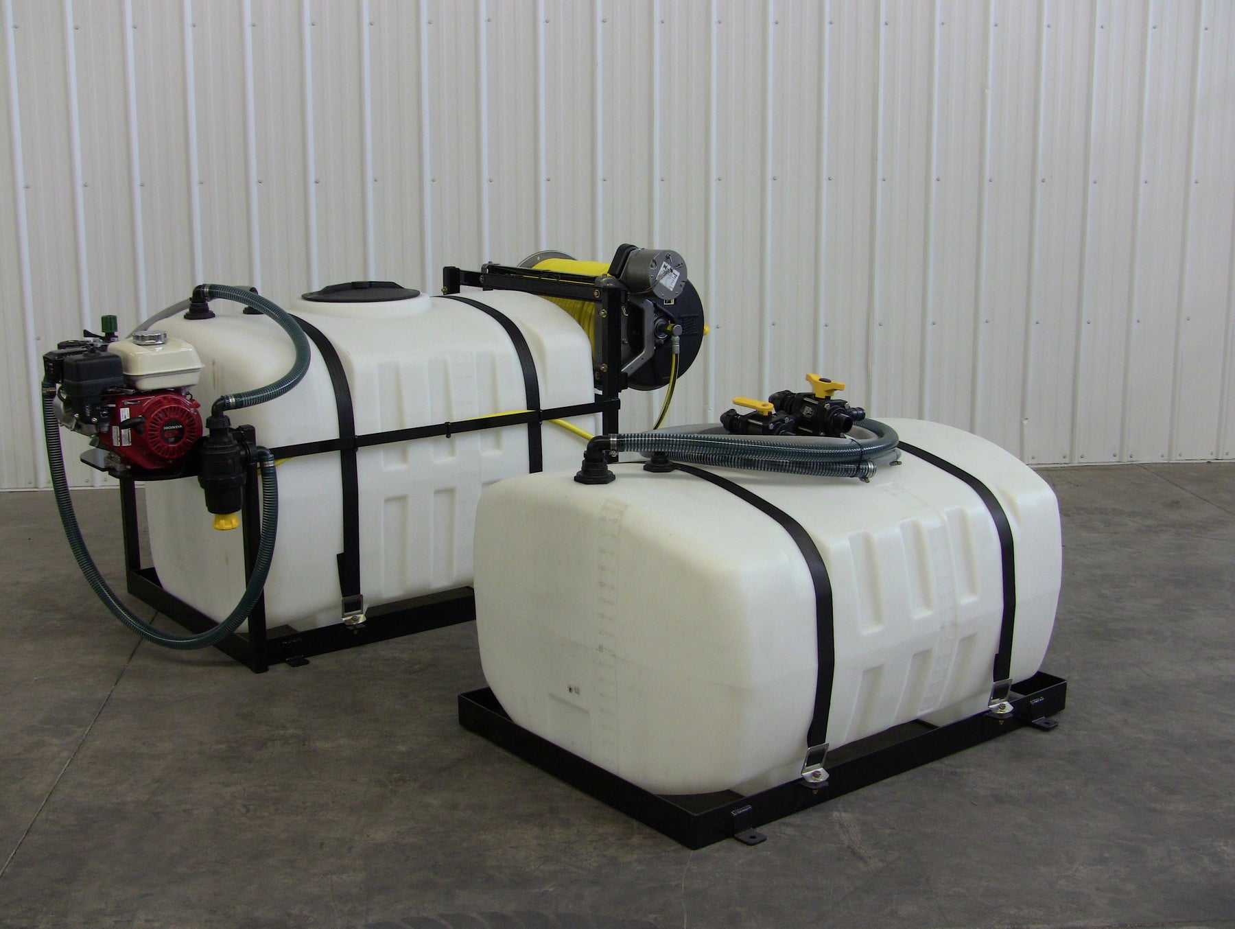
Whether you’re looking to run separate products or just add capacity to your existing system, the 3-way valve kit along with a modular tank from Gregson-Clark allows operators a wide range of possibilities.
With a modular tank and 3-way valves you are able to draw from tank 1 or tank 2 or transfer liquids between tanks. You cannot draw from both tanks at once.
To install the valves you will need to start by removing the existing suction and agitation lines along with hose barbs from the top of the tank.
Tip: Warming up the hose on the barbs with a heat gun will help in removal.


With the hose and barbs removed, replace barbs with the 3-way valves. Each valve will have a threaded nipple on the bottom that will thread into the existing tank fittings. When installing, use a pipe sealant or Teflon tape to seal the threads. On the ¾” valve, the straight hose barb on the side will need to be removed to spin on the valve. Once the valve is set, re-install the hose barb using a pipe sealant. When positioning the valves make sure the side barbs are pointed in the same direction as the barbs that were removed. The old hose will re-connect to these barbs.
Re-install the hose we previously removed from the main tank onto the side barbs of the valves. These are the common or constant lines and will always be in use.


When purchasing the 3-way valves with a modular tank, the tank will be plumbed with 8 feet of suction and agitation hose to be hooked up to the valves. Different installations will require different hose lengths; the 8’ of hose can be cut shorter for your specific setup.

The hoses coming from the modular tank will connect to the top of the valves using the 90 degree hose barbs with fly nuts. The hose barbs will need to be installed after your desired hose length has been cut.
Tip: Using a heat gun to warm the hose will make installation much easier. Using silicone on the suction barb will help provide and airtight seal.
Connect the 1 ¼” barb and fly nut to the top of the suction ball valve and the ¾” line to the top of the ¾” valve.

With all the components installed you can now test the system. The valve handle position will dictate which tank is the supply tank and which tank is the return. When both handles are pointed up the system is pulling from the modular tank. When both levers are horizontal the system is working off the main tank which the 3-way valves are attached to. When you have one handle horizontal and the other vertical you will be drawing from one tank and returning to another.
For any questions regarding adding a modular tank to your existing sprayer please call us at 1-800-706-9530.